|
|
||||||
|
||||||
Building a remote controlled WALL-E robotby Andrew KirillovThe article describes hobby building of WALL-E robot and writing application for its remote control. |
Posted: March 22, 2010 Programming languages: C# AForge.NET framework: 2.1.2 |
|
Sample application (sources) – 76.6K 
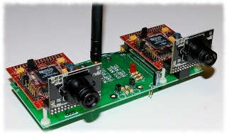
IntroductionIt is funny to note how movies inspire robotics builders – hobbyists always tend to build their favourite robots from many different movies. Such famous robots like R2-D2, Johnny 5, WALL-E and others were recreated many times by hobbyists every time having something special and interesting in their implementation. And it is really nice that more and more of such robots are coming, since nowadays many different manufacturers provide wide range of electronics, robotics kits, hardware parts, etc., which are used by many robots’ builders for their hobby, research, fun, etc. Fun, unless somebody recreates famous T-800 … 🙂 Similar happened to me. After switching from Lego robotics kits and trying building some robots on my own, I decided to continue and to building a robot, which became quite famous not so long ago – WALL-E. Of course my implementation was not supposed to become 100% replica of it (still need to get more experience in such type of hobby projects), but at least I wanted to get kind of “Wow, it is WALL-E” reaction from somebody how takes a look at it. So, let’s get it done! Nuts and bolts and wires …One of the key things to think about starting a new robotics project is what would become a brain for the robot, i.e. the CPU/electronics part which would handle all the robot’s hardware like motors, servos, sensors, cameras, etc. And when it comes to robots like WALL-E, it becomes very important because of the fact that this robot has 2 eyes. Of course the issue is not critical at all, if you plan to put something what mimics eyes instead of more or less real eyes. But this is really not so interesting and not something I wanted to do. So, if we want to give our robot’s vision, then we need to use cameras. Or, to be precise, we need two cameras. The fact that we are going to give computer vision to our robot puts some hard constraints in selection of its “brains”. There are not many vision enabled robotics kits (affordable to hobbyists) on the market yet, so choice is quite limited. I though about borrowing Qwerk robotics board from my previous robot, but it allows connecting only one camera, which does not seem to be enough for WALL-E (unless it is not a pirate). Another option could be using small laptop, like EeePC, but it would increase robot’s size and weight. Luckily the solution comes from Surveyor company, which provides its Stereo Vision System (SVS) board aimed for robotics applications and with 2 camera on board! The board also provides wireless connectivity (which I really wanted for remote control) and allows connecting some motors, servos and sensors. So, one single board provides all we need for a robot like WALL-E.
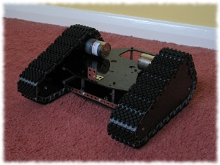
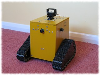
OK, we got brains and eyes, so now we need to take care of motion. What would be a WALL-E robot if does not have triangular shaped tracks? Not wheels or just some random tracks, but triangular shaped tracks. This time we may need going to Lynxmotion company, which produces lots of stuff designed for robotics applications, and get its Tri-Track Chassis Kit.
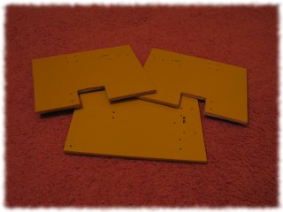
Now, when we have eyes and “feet”, the next step is to get WALL-E’s body. Although it has quite simple box shaped body, the step was the most challenging for me. And the reason for this is that the body was not bought as yet another robotics kit, but it was handcrafted. Apparently I don’t have a full featured workshop at home, but just a more or less conventional kit of screwdrivers, files, drills, a saw, etc. So it was a bit of challenge to make all the pieces manually and fit them together so they look nice. Started from sawing, filing, then trying to fit and again filing, then drilling and finally colouring to yellow …
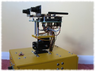
Before attaching WALL-E’s head to its body, we may need to get few servos and some mounting hardware. The easies way is to go back to Lynxmotion and get its Pan and Tilt Kit.
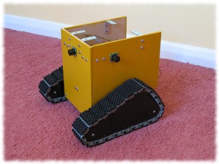
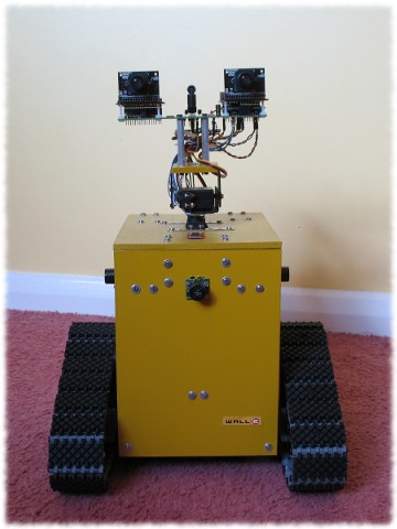
Finally, after putting all together, comes the final WALL-E’s look …
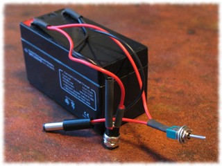
Yes, it does not have arms like the real WALL-e and the eyes’ shape does not look the same. But it still looks quite nice for the first try. However, there are few additional things which were given to the robot: 4 Maxbotics’ EZ1 ultrasonic range funders (one per each side), so it could measure distance to obstacles, and a Honeywell’s HMC6352 compass (put on top) to give some sense of orientation. The final thing is a rechargeable 12V 3AH/20HR battery, which I’ve borrowed from my last robotics project.
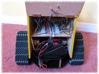
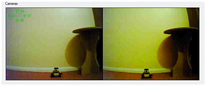
As we may see on the last picture, the robot’s back side was made in the form of a door, so it could be easily opened and provide access to all the robot’s wires. One additional thing to note is that I’ve use two commutation blocks, which join all the wires coming from different sensors/motors with wires coming from SVS side. This was done with the aim of reducing amount of soldering and making it easer to swap wiring in the case of any possible issues. Software partNow, when the hardware part is done, we’ll go to the software part – manipulating the robot from an application running on PC side. (If there is no interest in this part, just skip it and watch a video of WALL-e in action). As it was shown in my previous article, writing application for controlling Surveyor Stereo Vision System board is quite easy, especially with its support by AForge.NET framework. The framework provides access to all features of the board, like access to motors, servos, sensors, cameras, etc. plus it gives some extra tools, which simplify displaying of video streams and controlling of robot. As a first thing to do we need to connect to our robot and get its view – what it observes with its cameras. For all type of SVS board’s access we’ll need to use SVS class and for displaying video we’ll use a helper VideoSourcePlayer control: SVS svs = new SVS( ); // connect to robot svs.Connect( host ); // enable safe mode, which stops motors if connection is lost svs.EnableFailsafeMode( 0, 0 ); // make sure video is not flipped svs.FlipVideo( false ); // set video quility and resolution svs.SetQuality( 7 ); svs.SetResolution( SRV1.VideoResolution.Small ); // start left camera SRV1Camera leftCamera = svs.GetCamera( SVS.Camera.Left ); leftCameraPlayer.VideoSource = leftCamera; leftCameraPlayer.Start( ); // start right camera SRV1Camera rightCamera = svs.GetCamera( SVS.Camera.Right ); rightCameraPlayer.VideoSource = rightCamera; rightCameraPlayer.Start( );
The next step is to give motion to the robot by driving its motors and pan-tilt servos. There is not much to say about how to do this, since all you need is to call AForge.NET framework’s RunMotors() or ControlServos() methods specifying motors’ power or servos’ position. However there is a bit to say about how to make it user friendly, so it is easy to manipulate the robot. The easiest way to manipulate such type of a robot is to use a game pad with at least two analog joysticks. I’ve got simple and cheap Saitek P380 gamepad, but there are many different kinds of similar devices. With such gamepad it becomes really simple and natural to manipulate your robot – one analog joystick becomes dedicated for running motors, but the second joystick is used to manipulating pan-tilt servos of camera, so robot can move and rotate its head simultaneously. From coding side everything seems to be quite simple as well, since AForge.NET framework provides Joystick class allowing to query status of game controllers. The class is a very simple wrapper of WIN32 API, so it does not provide notifications about joystick’s status changes. But it is quite easy to solve the issue by creating background thread or a timer for reading its game pad’s status:
if ( lastJoystickStatus == null )
{
    lastJoystickStatus = joystick.GetCurrentStatus( );
    return;
}
Joystick.Status status = joystick.GetCurrentStatus( );
// check if there are changes in joystick status
if ( ( status.Buttons != lastJoystickStatus.Buttons ) ||
     ( Math.Abs( status.XAxis - lastJoystickStatus.XAxis ) >= joystickThreshold ) ||
     ( Math.Abs( status.YAxis - lastJoystickStatus.YAxis ) >= joystickThreshold ) ||
     ( Math.Abs( status.ZAxis - lastJoystickStatus.ZAxis ) >= joystickThreshold ) ||
     ( Math.Abs( status.RAxis - lastJoystickStatus.RAxis ) >= joystickThreshold ) )
{
    HandleJoystickStatus( status, lastJoystickStatus );
    lastJoystickStatus = status;
}
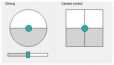
Everything is really nice and easy when you have a game pad to control your robot. But what if you don’t have it? It is possible to use a keyboard for this or put some buttons on a form like “Move Forward”, but all these will not give similar feel as with using joystick. I had similar issue building my first robots a while ago and wanted to get closer to analog joystick, but using PC mouse only. For these purpose I’ve implemented two controls, which finally became part of AForge.NET framework, so potentially the approach could be reused by somebody else. The first control, ManipulatorControl, really mimics behaviours of analog joystick. It has a manipulator, which can be moved away from centre in different directions. The control fires events on manipulator’s movement and an event handler simply translates its coordinate to motors’ power or servos’ position in similar way like it is done for joystick. The second control, SliderControl, is an additional helper control, which makes it easy to perform such movement actions like rotating on place, when one robot’s motor rotates in one direction, bet the second motor rotates in the opposite direction. By dragging slider’s manipulator away from centre, it is possible to control direction of robot’s rotation and its speed.
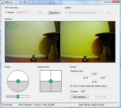
The final step is to get robot’s sensors working. With ultrasonic range finders everything is very easy – just use UltrasonicPing() method, which returns values from up to 4 sensors. But with compass I’ve stuck for now. The issue is not in reading compass’ values – it is easy. Since compass sensor is an I2C device, we may just use I2CReadWord() method to read its values. But the problem actually is in those values itself. Since compass reacts on magnetic field of the Earth, it is very sensitive to any magnetic disturbances, which can be caused, for example, by magnets used in robots’ motors. Although I’ve put a layer of aluminium foil inside of WALL-E’s body and connected it to a ground pin of SVS board, it did not help much. Also I’ve tried calibrating the compass using the procedure described by its manufacturer, but did not get much success either. So for me it looks like it happened similar as with other robotic hobbyists – the compass became a bit redundant part of the robot. At least for now … The attached to the article code provides all additional details about the application I made for my WALL-E clone. So it may be studied more if there is any interest to it. And here is the final look of the application.
Finally, lets get some fun and see it in action on YouTube! ConclusionThe WALL-E clone project became my biggest robotics hobby project so far. Lots of new hardware/electronics were studies plus this project required much more handcrafting than I did before for any other of my previous robots. All these were fun, interesting and challenging at the same time. And what I like even more is that it allowed me to progress my robotics experience some more, so doing my next robotics project I will try reusing all the knowledge and bring it to the next quality level. One of the things, which I would like to avoid in my next project, is a closed box like design of robot’s body. Although I’ve put a door on WALL-E’s back side, which could be easily opened to provide access to all the wiring, the amount of space there is very little, which makes it hard to work with a screwdriver or other tools inside of the robot’s body. Initially it was supposed that the panel with wires’ commutation blocks could be easily taken out, so all repairs could be done outside. But as it turned out it is not so easy when length of some wires does not allow doing so. Anyway, the idea of next design will try to cover the issue, so the robot will be more open and/or provide easy access to any of its parts. Another thing to note is a bout Surveyor’s Stereo Vision System. The board is really nice and gives a good start to many robotics projects made by hobbyists and researchers. One of the things it would be nice to improve there is to somehow separate video related communication with the rest of functionality (although it is not possible with its current architecture). The problem which I came across is related to the fact that SRV-1 architecture is kind of single threaded, so one connection to camera is used for both video and the rest – manipulating motors, servos, sensors, etc. So, if SRV-1 device is busy with handling of the next video frame, it will not react on motors related commands. This means robot may not stop at the moment you say it to stop. Another effect which may happen is that frame rate of one of the cameras (those which is also used for sensors, motors, servos) may drop a bit compared to another camera. Although the manufacturer says it will be hard to notice it, in reality it will be seen, especially when one of the cameras handles much more than just video. |
|||||||||||||||
|
|
|||||||||||||||