|
|
||||||
|
||||||
Making a step to stereo visionby Andrew KirillovThe article discusses building pan-tilt platform with 2 web cameras, which is aimed to allow experimenting with some stereo vision applications. |
Posted: January 17, 2009 Programming languages: C# AForge.NET framework: 2.0 |
|
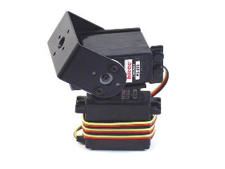
Sample application (sources) – 106K Sample application (binaries) – 123K IntroductionAs we’ve discussed some time ago, pan-tilt cameras are much more fun than regular static cameras. Among different applications in video surveillance, they can be applied in many different computer vision applications, which include tracking of different objects, tracking of human face in human-computer interaction task, etc. There are many different pant-tilt cameras available from different cameras’ manufacturers, which provide a broad selection of cameras for all sort of possible applications. But, if you are a hobbyist, you may want to build a pan-tilt camera on your own, which is fun process. Especially this may be required if you work with robotics stuff, which may require a custom built pan-tilt camera suiting your robot’s design. In the past we’ve already discussed building a custom pan-tilt camera, which was made using Lego NXT robotics kit. It was relatively easy and simple to build the pan-tilt device from Lego bricks, but it was a bit too big and awkward. This time we will try building another pan-tilt camera using smaller dedicated pieces, which better suite the task and allow much better camera manipulation. Another nice feature of the camera we are going to build is the fact that it will have two cameras actually, which would allow us to start experimenting with some applications from stereo vision area. Building pan-tilt moduleTo build our custom pan-tilt module we are going to use parts from different manufacturers, which provide kits and accessories for robots’ building. The easiest way to build pan-tilt module is to use already prepared kit, provided by Lynxmotion. Their kit includes two servos and corresponding mounting parts, which allow building the pan-tilt device very easily and quickly.
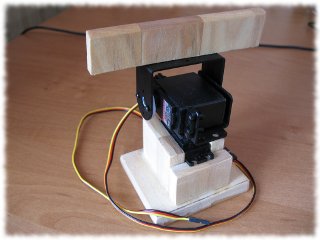
Since I did not have special mounting surface, I just built wooden box where the pan-tilt module could be inserted to be stable and not to fall when servos start to move. One the top of the module I’ve also placed another wooden part, which is prepared for mounting cameras (when we come to cameras discussion, it will become clear why such assembly was chosen).
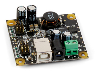
The next thing we need to do is to get servo controller, which could be used to control servos of the pant-tilt module we just built. For this we may go to Phidgets, which provide great range of different sensors, interface boards and motors/servo controllers. The nice things in Phidgets’ stuff, is that it can be plugged directly into USB port of your PC and easily programmed using wide range of programming languages with the SDK provided by this company. To control the pan-tilt module we’ve built, we may get the Phidget Advanced Servo controller for 8 motors. This controller allows us to control servos with quite high accuracy – 125 steps per degree, which means we don’t need to build awkward constructions with lots of gears like it was before with Lego robotics kit.
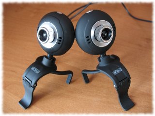
Using Phidgets’ SDK, it is very easy to start programming different controllers, interface kits and sensors provided by the company. More of it – there is support of great range of programming languages, samples applications and API documentation provided. As an example, below we may see a quick sample of controlling servo with the Phidget Advanced Servo controller. For the sake of code simplicity, we’ve used here waitForAttachment() method, which may block your application if the device is not attached. In real applications it is preferred to use AdvancedServo.Attach event, which notifies about successful attaching to Phidgets’ device. using Phidgets; using Phidgets.Events; ... // create advanced servo controller's object AdvancedServo servo = new AdvancedServo( ); // open the device and wait for attachment servo.open( ); servo.waitForAttachment( ); // set servo's velocity and acceleration servo.servos[0].VelocityLimit = 15; servo.servos[0].Acceleration = servo.servos[0].AccelerationMin; // set servo's position servo.servos[0].Position = 45; // turn on the servo, so it starts moving servo.servos[0].Engaged = true; To simplify the build process, all the parts may be ordered in one place – instead of ordering from both Phidgets and Lynxhmotion, you may just get the complete kit from Trossen Robotics, which includes as servos, as mounting kit, as the servos’ controller. Getting view from camerasInitially it may sound as an easy task to select cameras for the simple home built stereo vision setup, but it may appear not. The simplest and cheapest approach is to get two USB web cameras. But this approach may lead to some issues. For stereo vision applications, we need to make sure that video quality, contrast, resolution, etc. are the same from both cameras, otherwise we may get different complexity processing images from cameras looking for some similarities, etc. The best way to get same video properties from both cameras is to get two identical cameras – same camera model from the same manufacturer. With two identical USB cameras the hardest thing is not to buy them, but make them work together simultaneously. I heard a lot on different forums, that very often people have issues working with two identical USB cameras. In some cases camera drivers don’t allow/support viewing both cameras simultaneously – you may watch one camera or another, but not both. It is hard to say exactly which cameras are affected by the issue, which are not, but most of such issues I’ve heard were about Logitech cameras. Since Logitech cameras usually are more expensive and are surrounded by such sort of issues, I decided not to experiment with them and I got two quite cheap and simple cameras to try.
Working with USB cameras using AForge.NET framework is very simple. All we need to do is to enumerate available devices using FilterInfoCollection class and then play them using VideoCaptureDevice class and VideoSourcePlayer control:
// list of video devices
FilterInfoCollection videoDevices = new FilterInfoCollection(
                        FilterCategory.VideoInputDevice );
// create video source
VideoCaptureDevice videoSource = new VideoCaptureDevice(
                        videoDevices[0].MonikerString );
// setup control and start playing
videoSourcePlayer.VideoSource = videoSource;
videoSourcePlayer.Start( );
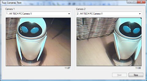
The very first test of these cameras was successful – they worked both simultaneously. But one of subsequent tests brought a crash – stack overflow exception in background thread created by VideoCaptureDevice class. That was disappointing taking into account that there were no any recursions or extensive usage of stack – just a crash calling rendering method from DirectShow interop classes. Doing more experiments, it was discovered that the exception is very rare – it was occuring once per 10 tests or even rarer. Initial thought was just to handle the exception by catching it and restarting the video source. But the idea has failed, since starting from 2.0 version .NET framework does not allow handling stack overflow exceptions. Another idea was just to increase stack size for the background thread. But it has failed too – setting stack size to several megabytes did not solve the issue. Now it looked like an issue with camera drivers. Fortunately I’ve managed to solve the crash issue for my USB web cameras – just put a small sleep between starting two cameras waiting for half a second. It is hard to say what is going wrong with cameras drivers, but it looks like they definitely don’t like starting two cameras immediately one after another. I am not sure if the small sleep is a panacea for solving issues with double camera setup, but at least I did not get crash with my setup so far. To make tests of two cameras’ setups easer, AForge.NET framework provides a small sample application, which demonstrates how to display two USB cameras. It allows to select cameras you would like to view, hit start and see the result …
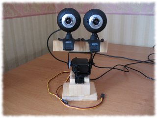
Now, when we have two cameras and pan-tilt module, it is time to assemble them together. Taking a look at the below pictures it is getting clear why the pan-tilt module was built with the wooden part on top – we use it to clip cameras to it, since our cameras were designed with a clip for attaching to laptop.
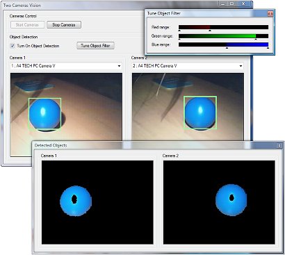
Note: Since the setup we built is going to be used for stereo vision applications, it is very important to mount cameras very accurate, so all their axes are parallel. Detecting an objectIt is time to experiment a bit. For the start let’s detect some object. Since an object is observed by two cameras from different positions, it will also have different position in images acquired from cameras. The difference in object’s coordinates in two images may be used to estimate the distance of the object from cameras. For example, if the difference is big, then the object is close to cameras, but if the difference is small, then the object is away from cameras. But let’s keep it for further discussion and just detect object for now. The simplest object detection may be achieved by utilizing color filters (see ColorFiltering, HSLFiltering, YCbCrFiltering filters for example), which could be quite successful for detecting/locating objects of solid color. All we need to do in the case of RGB filter, for example, is to specify ranges for each color component – colors which fall into the range will be kept, the rest will be filled by specified color. // create filter ColorFiltering colorFilter = new ColorFiltering( ); // configure the filter colorFilter.Red = new IntRange( 0, 100 ); colorFilter.Green = new IntRange( 0, 200 ); colorFilter.Blue = new IntRange( 150, 255 ); // apply the filter Bitmap objectImage = colorFilter.Apply( image );
Getting object position and dimension is very simple and may be done using BlobCounter tool, which finds stand alone objects. Since the class works with grayscale images, we need to apply one of grayscaling filter before, GrayscaleBT709 for example. Once objects are located, get the biggest one and process it somehow (highlight it, for example):
// create blob counter and configure it
BlobCounter blobCounter = new BlobCounter( );
blobCounter1.MinWidth = 25;                    // set minimum size of
blobCounter1.MinHeight = 25;                   // objects we look for
blobCounter1.FilterBlobs = true;               // filter blobs by size
blobCounter1.ObjectsOrder = ObjectsOrder.Size; // order found object by size
// grayscaling
Bitmap grayImage = grayFilter.Apply( objectImage );
// locate blobs
blobCounter.ProcessImage( grayImage );
Rectangle[] rects = blobCounter.GetObjectRectangles( );
// draw rectangle around the biggest blob
if ( rects.Length > 0 )
{
    Rectangle objectRect = rects[0];
    Graphics g = Graphics.FromImage( image );
    using ( Pen pen = new Pen( Color.FromArgb( 160, 255, 160 ), 3 ) )
    {
        g.DrawRectangle( pen, objectRect );
    }
    g.Dispose( );
}
To make object detection experiments easer, the attached to the article application provides easy to use user interface, which allows configuring color filter and see result of its application to video feed.
Synchronizing camerasIf we work with two cameras, then most probably each of the cameras is handled by its own background thread, which does image acquisition from cameras and then their processing. This if fine as long as we just need to display video data in separate controls and don’t need to process images from both cameras in couple. But if we need to perform coupled image processing of two images acquired from different cameras, then we may need to synchronize cameras’ threads somehow. One possible solution is to block one of the cameras’ threads until the second thread also prepares new image from camera and informs about it by setting an event for example. But this approach is not nice because of several reasons. First of all the first thread may be locked for quite a while if something happens with the second camera. Another bad point is that we will do image processing of both images in the first thread, which means it will be frozen for a while and will not acquire new images. The better approach is two let both cameras’ threads to acquire images and do their preprocessing and then let another thread to perform stereo vision routines doing coupled processing of images from two cameras. This will give much better load balancing of threads and will not block image acquisition threads from their work. The approach just requires two events, which are used to synchronize acquisition threads and processing thread – acquisition threads set the event informing about new available image and the processing thread waits for both events to start its work on coupled processing of both images:
// background thread for stereo vision routines
...
    while ( true )
    {
        // wait until we have two acquired images
        camera1Acquired.WaitOne( );
        camera2Acquired.WaitOne( );
        ...
    }
Object trackingNow, when we have detected object, let’s track it utilizing our pan-tilt module. First of all we need to calculate object’s center relative to image center (we use Cartesian coordinate system for this). Also lets map both X and Y coordinates to [-1, 1] range. So, if coordinates are (X=0, Y=0), then the object is right in the center of the image. If coordinates are (X=-1, Y=-1) then the object is in the left bottom corner. This calculation may be done in acquisition threads, since they still don’t require coupled image processing: // for the first camera, for example // calculate X,Y coordinates of object's center x1 = ( objectRect.Left + objectRect.Right - objectImage.Width ) / 2; y1 = ( objectImage.Height - ( objectRect.Top + objectRect.Bottom ) ) / 2; // map to [-1, 1] range x1 /= ( objectImage.Width / 2 ); y1 /= ( objectImage.Height / 2 ); The final calculations are done in the tracking thread. To be able to track the object, we need to calculate average of object’s coordinates acquired from different cameras. The middle point is used because we don’t want the object to be centered in one of the cameras’ views. Instead of this we want the center of the object to be right opposite to the middle point between cameras.
// background thread for object tracking
...
    float targetX = 0;
    float targetY = 0;
    while ( true )
    {
        camera1Acquired.WaitOne( );
        camera2Acquired.WaitOne( );
        lock ( this )
        {
            // get middle point
            targetX = ( x1 + x2 ) / 2;
            targetY = ( y1 + y2 ) / 2;
        }
        ...
    }
The coordinates mapping to [-1, 1] range was done intentionally. When we have such coordinates, it is quite easy to covert them to rotation angles for both servo motors, which are used in pan-tilt module. The greater are coordinate, the further away the object from center – the bigger rotation angle should be used … // run motors for the specified amount of degrees (max 2 deg.) RunMotors( 2 * targetX, -2 * targetY ); And finally, let’s see all these in action … ConclusionWell, it was quite fun and interesting to build the pan-tilt module with two cameras and then apply it to object tracking task. Building it and experimenting with it allows to learn many different things about servo motors, motor controllers, cameras, basics of stereo vision, etc. Of course the article does not provide deeper insight into stereo vision problems, but it was not the aim. The aim of this article was to give a start to stereo vision applications by building setup first, which is going to be reused further for solving more complex problems. I believe it was done quite well. So, see you next time with continuation. |
||||||||||||
|
|
||||||||||||