|
|
||||||
|
||||||
Hobby built car-like robotby Andrew KirillovThe article discusses building car-like robot, which is based on Qwerk robotics board and set of other electronics/hardware. |
Posted: June 30, 2009 Updated: July 23, 2009 Programming languages: C# AForge.NET framework: 2.0 |
|
Sample application (sources) – 107K 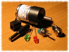
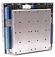
IntroductionIt has passed a while since the time I got interested in robotics and started building some stuff. Initially, as many other novice hobbyists do, I started with something simple and tried different Lego Mindstorms Robotics kits, like RCX and NXT. These kits are really easy to start with and allow building many different things, like car-bots, pan-tilt cameras, etc. But eventually you may want trying something more sophisticated, which could result in a robot with wider range of features. To get most flexibility and also enjoy building robots on your own, it is much more preferred to switch from kits like Lego, to some more specialized hardware, like different motors, servos, sensors, controllers, robotics boards, etc. Of course it will not be that easy as with plug-n-play Lego kits, but it may allow us designing our own robot putting the hardware we want for tasks we need. Going this road we need to be a bit prepared and get some simple tools like screwdrivers, soldering tools, wire-cutters, maybe a small saw, files, etc. It may end up in real building, which is real fun! One of the easy things to use for building your custom robots is a range of different controllers and interface boards provided by Phidgets. These are very nice things which can be plugged into computer’s USB port and programmed very easily with SDK provided by the company. Last time I’ve tried Phidgets for building pan-tilt module for a simple stereo vision setup. This worked really nice and I definitely consider building more on their base. But this time I was interested in building mobile robot and I did not want making PC (even a tiny notebook like EeePC) part of my robot. Instead of this I wanted to get something, which is not so big in size and could be controlled over Wi-Fi. In order to achieve this goal, I made my choice in using Qwerk. I was already writing about Qwerk board in the past and the way to control it remotely. This is really nice peace of manufacturing, which allows building quite sophisticated robots carrying bunch of sensors, servos, motors, etc. This time it will be used for building mobile robot controlled remotely over Wi-Fi.
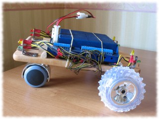
What are we going to build ?This time we are going to build a remotely controlled car robot, with the next list of features:
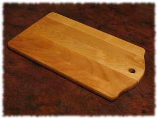
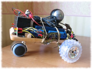
It should be really nice, when all the above is done and works! Let’s start buildingThe baseOne of the fun things in building something as a hobby is building everything on your own using all sort of stuff you can find around and can make use of. For example, building a robot you may find that different stuff left after flat repairing will work fine, as well as old broken child’s toys, electronics, etc. Sometimes it may be hard to find a specialized part for the robot you build or it may be not that cheap buying dedicated stuff out of a set. So, building a robot I always take a look around the flat for something, which may become useful. This time it happened with robot’s base. I was looking for something, which could be used to attach wheels to and carry all the robot’s stuff. And I found that a small cutting board looks so nice as a robot’s base … Yes, sounds crazy – cutting board used in robotics. But I could not resist when I found that accidentally in a regular shop and imagined my robot with it.
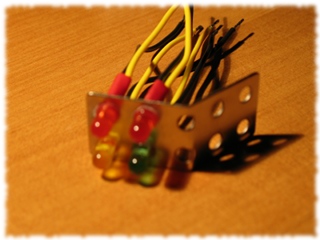
The lights One of the fun features of the car robot we build is lights. The idea is that the robot should mimic a real car and be equipped with lights similar to those we have on our cars. For this purpose we are going to use LEDs of different colors:
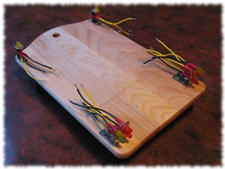
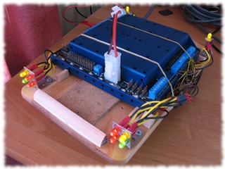
So, in total we’ll have 12 LEDs. The picture below on the left shows one of the lights’ racks used on rear side of the car robot we build – 2 stop lights, 1 turn and 1 dimension light. The picture below on the right shows all lights attached to the robot’s base.
Turn the lights on To turn the lights on we need to do some wiring and connect all of the lights to the Qwerk board. We’ll use 4 digital outputs of the board to control independently all stop light, all dimension lights, 2 turn lights on the left and 2 turn lights on the right. The first mistake I made here was connecting 4 LEDs into a daisy chain. It will not work, since digital outputs’ voltage is not enough to power it. In order to make it work we need to use parallel connection for LEDs which we want to connect to single Qwerk’s digital output. And it is even better since it makes sure that entire chain will not go down if single LED gets broken.
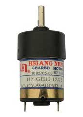
The wheels As I already mentioned, the car we are building will have two motors which are used to drive it in different directions. For this purpose we can use any geared motors, which can be ordered in plenty of electronics store, for example Active Robots. I’ve used two 12 Vdc 595 RPM motors:
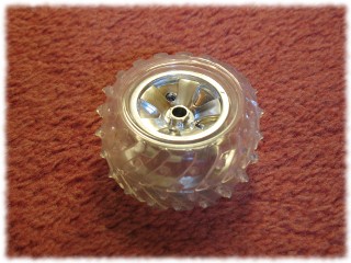
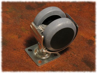
The next thing to get is wheels. Here it all depends on what you (or maybe your kids) have at home or you can find in stores. Personally I used two wheels from my kid’s old radio car attaching them to front motors – big nice wheels. For the rear I used only one wheel, which I bough in local furniture store (since it is one, it goes in the middle).
Well, since we build the car manually and all our pieces come from different sources, sometimes it happens that something may not fit together very well. Similar thing has happened with my wheels – the rear wheel seems to be a bit taller, which makes car’s rear part to be raised above its front part. But, this is not that critical and I hope it will still move fine.
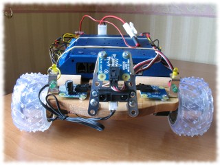
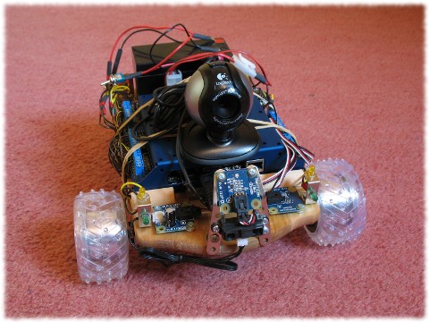
Sensors The next step is to put some more electronics on board of the car – put some sensors. We are going to put 3 sensors which are all obtained from Phidgets:
Of course all the Phidgets connection cables are not designed for Qwerk, they are designed for Phidgets boards. But with the help of wire-cutter it s possible to rework one original Phidgets connector into two connecters, which allow to connect Phidgets sensors to Qwerk board.
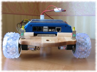
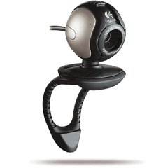
Camera The next step to do is to give this car an eye, so we could get vision. The Qwerk board, which is central piece of the car we build, has 2 USB ports. One of them is supposed for a regular USB camera. Well, I am actually lying by saying regular USB camera. Unfortunately Qwerk’s firmware does not support big list of USB cameras, but it supports quite limited list. The list of supported devices can be found on the TeRK’s project page. I was lucky and got Logitech Communicate STX camera few years ago and it works fine with Qwerk. But it may become a problem for somebody, who does not have camera like this, since all new cameras may not be supported by Qwerk, but getting older camera may not be simple. So, at this point all we need to do is to plug the camera into Qwerk, test that it works with TeRK software and we’ll return back to the topic later, when we get to programming section.
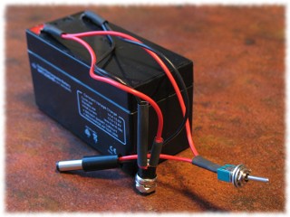
Going to wireless The last and actually quite important step is to make the car wireless. To do this we need wireless power and wireless communication. To provide power to the car, I used rechargeable 12V 3AH/20HR battery. Just added two connecters to it – one for Qwerk and one for charger.
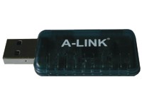
It so happened that getting wireless communication was the hardest part. This was caused again by the fact that Qwerk board supports limited amount of USB wireless adapters – only adapters, which are based on zd1211b chipset. And the trick is that it may not be so simple to find such adapters. I’ve tried few of them, but got luck only with A-LINK adapter, which I’ve found by accident in local store. Once you get zd1211b chipset based adapter, just plug it into the Qwerk board, turn it on and enjoy. One more important note – we need to use DHCP (even for Qwerk’s Ethernet adapter), otherwise Qwerk’s network script will get confused (of course you may log into Qwerk, since it is running Linux, and try to edit/write better network script, but it was not something I wanted to do this time).
Well, it looks like we’ve finished with all the hardware. Now it is time to make it work by writing software to manipulate the robo-car.
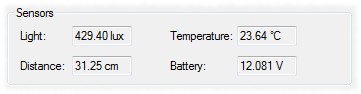
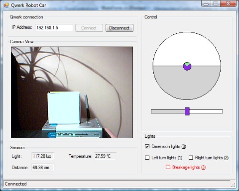
Writing software to control the carI’ve already wrote an introduction article about Qwerk in the past, where it was shown how to write C# application to manipulate Qwerk device. That article discusses the Ice framework, which is used to communicate with Qwerk, how to convert TeRK’s Slice interfaces into C# proxy classes and how to use them. We could go the same road this time, but I would prefer to go a bit away from all that stuff. Not so long ago, the AForge.NET framework has introduced an AForge.Robotics.TeRK namespace, which provides set of classes to manipulate Qwerk devices. Of course this namespace does not free us from installing Ice framework, but it hides all the Ice related stuff, wrapping it into nice interface and providing additional API, which seems to be much easer in use. So, let’s use the framework. As usual, the first thing we need to do is to connect to Qwerk device. For this purpose we need to use Qwerk class from the TeRK namespace: // create Qwerk's instance Qwerk qwerk = new Qwerk( ); // connect to Qwerk qwerk.Connect( "192.168.0.5" ); The next thing we may want to do is to get view from Qwerk’s camera, which is really simple to do with the framework. For this purpose we need to use VideoSourcePlayer control, which does rendering of video feeds, and Qwerk.Video class, which does actual video frames’ retrval: // get Qwerk's video servce Qwerk.Video qwerkVideo = qwerk.GetVideoService( ); // set desired interval between video frames qwerkVideo.FrameInterval = 1000 / 15; // pass the video source to previously created VideoSourcePlayer control videoSourcePlayer.VideoSource = qwerkVideo; // start video videoSourcePlayer.Start( ); Now it is time to get values from our Phidgets sensors. To read analog inputs of Qwerk we need to use Qwerk.AnalogIn class – this is simple. But then we need to convert analog inputs’ values to some sort of meaningful values, like distance, temperature, etc. – for this we need to refer to specification provided by sensors’ manufacturer. Fortunately Phidgets always provides good documentation, so it is not a problem to figure out the conversion formulas. The raw sensors’ values provided by Qwerk are in millivolts, in the [0, 5000] range, and if we take a look into Phidgets specs, then we may find how to convert raw sensors’ values, to something what we can understand (note: Phidgets provides different conversion formulas for each sensor in their specs – we need to use the formula, which is for the case, when Phidgets sensor is connected to custom device, but not Phidgets interface board). Here is the code, which does all the conversions for our sensors – light, temperature and distance:
// get raw sensors' values
short[] sensors = qwerk.GetAnalogInService( ).GetInputs( );
// convert sensors' values to [0, 1000] range
double[] sensorValues = new double[sensors.Length];
for ( int i = 0, n = sensors.Length; i < n; i++ )
{
    sensorValues[i] = (double) sensors[i] / 5;
}
// temperature
double temprature = sensorValues[inTemperatureSensor] * 0.2222 - 61.111;
temperatureBox.Text = temprature.ToString( "F2" ) + " °C";
// light
double light = sensorValues[inLightSensor];
lightBox.Text = light.ToString( "F2" ) + " lux";
// distance
if ( ( sensorValues[inDistanceSensor] >= 80 ) &&
     ( sensorValues[inDistanceSensor] <= 500 ) )
{
    double distance = 4800.0 / ( sensorValues[inDistanceSensor] - 20 );
    distanceBox.Text = distance.ToString( "F2" ) + " cm";
}
else
{
    distanceBox.Text = "Unknown";
}
// battery
batteryBox.Text = string.Format( "{0} V",
    (double) qwerk.GetPower( ) / 1000 );
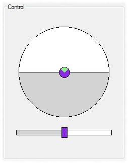
The next step is to take care of our car’s lights. All the lights are represented by LEDs of different colors, which are connected to Qwerk’s digital outputs. This means that we need to use Qwerk.DigitalOut class to enable/disable digital outputs in order to turn on/off the lights. All we need to write is a single line of code to turn on/off one light: // turn on dimension lights qwerk.GetDigitalOutService( ).SetOutput( ledDimensionLight, true ); And the final step is to let the car move. First of all I would like to say a bit about the way, how we control the car. To do this, we use two controls, which were already discussed in the past, when I wrote an article about Lego Robotics Kits – RCX and NXT. The first control is kind of “software” joystick – dragging mouse you may direct your robot straight forward, turn left or right or go back (also straight or doing a turn). All you need to do is to drag manipulator away from center, which results in setting appropriate speed for both motors. If manipulator goes further away from center, motors get more power leading to faster movement. If manipulator goes to right or left from center, then one motor gets more power than another, which leads to a turn. The second control is used only for turning the car – the control is used to provide the same power to both motors, but different directions (if one wheel rotates clockwise, then another one rotates counter-clockwise).
Finally, after converting manipulators’ positions to motors power we need to set it. For this purpose we need to use Qwerk.Motors class, which provides methods to control Qwerk’s motors:
// get Qwerk's motors service
Qwerk.Motors motors = qwerk.GetMotorsService( );
// check if we need to stop
if ( ( leftMotorVelocity == 0 ) && ( rightMotorVelocity == 0 ) )
{
    motors.StopMotors( );
}
else
{
    motors.SetMotorVelocity( 0, -leftMotorVelocity );
    motors.SetMotorVelocity( 1, rightMotorVelocity );
}
Well, of course all the above are just code snippets, but not the complete application. The purpose of these code snippets is to give an idea. But if you would like to get the full application, you are more than welcome to download article’s attachment (see on the top of the page).
And now lets take at the result we’ve got … ConclusionWell, I really must admit that it was a great experience to build such robot. Even though the robot itself does not look complex (yes, it is no Asimo), building something like this may become really interesting. After such robotics kits like Lego’s RCX or NXT, the Qwerk is totally different way of building robots. Yes, it is much harder on one hand – you don’t have all the ready to use bricks like Lego provides – you will need to make them on your own. But on another hand it keeps your imagination and creativity free – you may build whatever you want connecting much wider range of sensors, motors, servos, etc., than any other robotics kit provides. Of course the robot I’ve built does not look like something incredible these days. But it was the first experience of building something from scratch. Hope to benefit from it and not to make same mistakes next time building something new. Building the robot I learned many things. But one thing I would like to highlight – don’t start building your own robot if you don’t have more or less clear understanding of what you want to build and if you have some missing parts. That was the case with me – I started to build the robot without having all the required parts, like battery. And later, when I got my rechargeable battery, I figured out that my current robot does not have space for it … So it was required to rebuild it a bit. Taking into account that some robotics stuff may not be cheap to order, it is much better to avoid rebuilding. Another mistake, which was found later during testing phase, is related to rear wheel. Initially the furniture wheel looked nice and quite flexible. Also I’ve seen some other robotics projects, which used something similar. But in reality it does not work that nice as it looks. In reality it was a bit tough and was not that flexible under the robot’s weight. Also it gave some slope to robot’s base, which added some issues as well. The robot was moving forward with no issues, but going backward with such wheel was not so nice – sometime position of the wheel was leading to movement in directions, which were not very correct. Well, will keep thin in mind in the future … As I already mentioned in the previous article, it is not possible to get new Qwerk boards any more. Innovation First, the company which produces the VEX line of robotics products, has licensed Qwerk robotics controller, so now we are waiting for the new version. And it looks like release of the new produce is getting closer and closer. Here is some preliminary info about it. Would love to get it! |
||||||||||||||||||||||||
|
|
||||||||||||||||||||||||